The phenomenon of light refraction is a physical phenomenon that occurs whenever a wave travels from one material to another in which its speed of propagation changes. Visually, it manifests itself in the fact that the direction of wave propagation changes.
Physics: refraction of light
If an incident ray hits the interface between two media at an angle of 90°, then nothing happens, it continues its movement in the same direction at right angles to the interface. If the angle of incidence of the beam differs from 90°, the phenomenon of light refraction occurs. This, for example, produces such strange effects as the apparent fracture of an object partially submerged in water or mirages observed in a hot sandy desert.
History of discovery
In the first century AD e. The ancient Greek geographer and astronomer Ptolemy tried to mathematically explain the value of refraction, but the law he proposed later turned out to be unreliable. In the 17th century Dutch mathematician Willebrord Snell developed a law that determined the quantity associated with the ratio of the incident and refracted angles, which was later called the refractive index of a substance. Essentially, the more a substance is able to refract light, the greater this indicator. A pencil in water is “broken” because the rays coming from it change their path at the air-water interface before reaching the eyes. To Snell's disappointment, he was never able to discover the cause of this effect.
In 1678, another Dutch scientist, Christiaan Huygens, developed a mathematical relationship to explain Snell's observations and proposed that the phenomenon of light refraction is the result of the different speed at which a ray passes through two media. Huygens determined that the ratio of the angles of light passing through two materials with different refractive indices should be equal to the ratio of its speeds in each material. Thus, he postulated that light travels more slowly through media that have a higher refractive index. In other words, the speed of light through a material is inversely proportional to its refractive index. Although the law was later experimentally confirmed, for many researchers of that time this was not obvious, since there were no reliable means of light. It seemed to scientists that its speed did not depend on the material. Only 150 years after Huygens' death was the speed of light measured with sufficient accuracy to prove that he was right.

Absolute refractive index
The absolute refractive index n of a transparent substance or material is defined as the relative speed at which light passes through it relative to the speed in a vacuum: n=c/v, where c is the speed of light in a vacuum and v is the speed of light in the material.
Obviously, there is no refraction of light in a vacuum, devoid of any substance, and in it the absolute index is 1. For other transparent materials, this value is greater than 1. To calculate the indexes of unknown materials, the refraction of light in air (1.0003) can be used.

Snell's laws
Let's introduce some definitions:
- incident ray - a ray that approaches the separation of media;
- point of impact - the point of separation at which it hits;
- the refracted ray leaves the separation of the media;
- normal - a line drawn perpendicular to the division at the point of incidence;
- angle of incidence - the angle between the normal and the incident beam;
- Light can be defined as the angle between the refracted ray and the normal.
According to the laws of refraction:
- The incident, refracted ray and normal are in the same plane.
- The ratio of the sines of the angles of incidence and refraction is equal to the ratio of the refractive coefficients of the second and first medium: sin i/sin r = n r /n i.
Snell's law of refraction of light describes the relationship between the angles of two waves and the refractive indices of two media. When a wave moves from a less refractive medium (such as air) to a more refractive medium (such as water), its speed decreases. On the contrary, when light passes from water to air, the speed increases. in the first medium relative to the normal and the angle of refraction in the second will differ in proportion to the difference in refractive indices between these two substances. If a wave passes from a medium with a low coefficient to a medium with a higher coefficient, then it bends towards the normal. And if it’s the other way around, then it’s deleted.

Relative refractive index
Shows that the ratio of the sines of the incident and refracted angles is equal to a constant, which represents the ratio in both media.
sin i/sin r = n r /n i =(c/v r)/(c/v i)=v i /v r
The ratio n r /n i is called the relative refractive index for these substances.
A number of phenomena that result from refraction are often observed in everyday life. The “broken” pencil effect is one of the most common. The eyes and brain follow the rays back into the water as if they were not being refracted but coming from the object in a straight line, creating a virtual image that appears at a shallower depth.

Dispersion
Careful measurements show that the refraction of light is greatly influenced by the wavelength of the radiation or its color. In other words, a substance has many that can vary when color or wavelength changes.
This change occurs in all transparent media and is called dispersion. The degree of dispersion of a particular material depends on how much its refractive index changes with wavelength. As the wavelength increases, the phenomenon of light refraction becomes less pronounced. This is confirmed by the fact that violet refracts more than red, since its wavelength is shorter. Thanks to dispersion in ordinary glass, a certain splitting of light into its components occurs.

Decomposition of light
In the late 17th century, Sir Isaac Newton conducted a series of experiments that led to his discovery of the visible spectrum, and showed that white light consists of an ordered array of colors, ranging from violet through blue, green, yellow, orange and ending with red. Working in a darkened room, Newton placed a glass prism into a narrow beam that penetrated through an opening in a window shutter. When passing through a prism, light was refracted - the glass projected it onto the screen in the form of an ordered spectrum.
Newton came to the conclusion that white light consists of a mixture of different colors, and also that a prism “scatters” white light, refracting each color at a different angle. Newton was unable to separate the colors by passing them through a second prism. But when he placed the second prism very close to the first in such a way that all the dispersed colors entered the second prism, the scientist found that the colors recombined to form white light again. This discovery convincingly proved the spectrum which can be easily divided and combined.
The phenomenon of dispersion plays a key role in a wide variety of phenomena. Rainbows are created by the refraction of light in raindrops, producing a spectacular display of spectral decomposition similar to that found in a prism.

Critical angle and total internal reflection
When passing through a medium with a higher refractive index into a medium with a lower one, the path of the waves is determined by the angle of incidence relative to the separation of the two materials. If the angle of incidence exceeds a certain value (depending on the refractive index of the two materials), it reaches a point where light is not refracted into the lower index medium.
The critical (or limiting) angle is defined as the angle of incidence resulting in an angle of refraction equal to 90°. In other words, as long as the angle of incidence is less than the critical angle, refraction occurs, and when it is equal to it, the refracted ray passes along the place where the two materials separate. If the angle of incidence exceeds the critical angle, the light is reflected back. This phenomenon is called total internal reflection. Examples of its use are diamonds and the diamond cut promotes total internal reflection. Most rays entering through the top of the diamond will be reflected until they reach the top surface. This is what gives diamonds their brilliant shine. Optical fiber consists of glass “hairs” that are so thin that when light enters at one end, it cannot escape. And only when the beam reaches the other end can it leave the fiber.
Understand and manage
Optical instruments ranging from microscopes and telescopes to cameras, video projectors, and even the human eye rely on the fact that light can be focused, refracted, and reflected.
Refraction produces a wide range of phenomena, including mirages, rainbows, and optical illusions. Refraction makes a thick mug of beer appear fuller, and the sun sets a few minutes later than it actually does. Millions of people use the power of refraction to correct vision defects with glasses and contact lenses. By understanding and manipulating these properties of light, we can see details invisible to the naked eye, whether they are on a microscope slide or in a distant galaxy.
One of the ancient Greek treatises describes the experiment: “You need to stand so that the flat ring located at the bottom of the vessel is hidden behind its edge. Then, without changing the position of the eyes, pour water into the vessel. The light will refract on the surface of the water and the ring will become visible.” You can show this “trick” to your friends now (see Fig. 12.1), but you can explain it only after studying this paragraph.
Rice. 12.1. "Trick" with a coin. If there is no water in the cup, we do not see the coin lying at the bottom (a); if you pour water, the bottom of the cup seems to rise and the coin becomes visible (b)

Establishing the laws of light refraction
Let's direct a narrow beam of light onto the flat surface of a transparent glass half-cylinder mounted on an optical washer.
The light will not only be reflected from the surface of the half-cylinder, but will also partially pass through the glass. This means that when passing from air to glass, the direction of light propagation changes (Fig. 12.2).
The change in the direction of light propagation at the interface between two media is called refraction of light.
The angle γ (gamma), which is formed by a refracted ray and a perpendicular to the interface between two media drawn through the point of incidence of the ray, is called the angle of refraction.
Having carried out a series of experiments with an optical washer, we note that with an increase in the angle of incidence, the angle of refraction also increases, and with a decrease in the angle of incidence, the angle of refraction decreases (Fig. 12.3). If light falls perpendicular to the interface between two media (angle of incidence α = 0), the direction of light propagation does not change.

The first mention of the refraction of light can be found in the writings of the ancient Greek philosopher Aristotle (IV century BC), who asked the question: “Why does a stick appear broken in water?” But the law quantitatively describing the refraction of light was established only in 1621 by the Dutch scientist Willebrord Snellius (1580-1626).
Laws of light refraction:
2. The ratio of the sine of the angle of incidence to the sine of the angle of refraction for two given media is a constant value:
![]()
where n 2 1 is a physical quantity called the relative refractive index of the medium. 2 (the medium in which light propagates after refraction) relative to medium 1 (the medium from which the light falls).
We learn about the reason for the refraction of light
So why does light change its direction when moving from one medium to another?
The fact is that in different media light propagates at different speeds, but always slower than in a vacuum. For example, in water the speed of light is 1.33 times less than in vacuum; when light passes from water to glass, its speed decreases by another 1.3 times; in air, the speed of light propagation is 1.7 times greater than in glass, and only slightly less (about 1.0003 times) than in vacuum.
It is the change in the speed of propagation of light when passing from one transparent medium to another that causes the refraction of light.
It is customary to talk about the optical density of a medium: the lower the speed of light propagation in the medium (the higher the refractive index), the greater the optical density of the medium.
What do you think, the optical density of which medium is greater - water or glass? The optical density of which medium is lower - glass or air?
Finding out the physical meaning of the refractive index
The relative refractive index (n 2 1) shows how many times the speed of light in medium 1 is greater (or less) than the speed of light in medium 2:
![]()
Remembering the second law of light refraction:
![]()
Having analyzed the last formula, we draw the following conclusions:
1) the more the speed of light propagation changes at the interface between two media, the more the light is refracted;
2) if a beam of light passes into a medium with a higher optical density (that is, the speed of light decreases: v 2< v 1), то угол преломления меньше угла падения: γ<α (см., например, рис. 12.2, 12.3);
3) if a beam of light passes into a medium with a lower optical density (that is, the speed of light increases: v 2 > v 1), then the angle of refraction is greater than the angle of incidence: γ > a (Fig. 12.4).
Typically, the speed of light propagation in a medium is compared with the speed of its propagation in a vacuum. When light enters a medium from a vacuum, the refractive index n is called the absolute refractive index.
The absolute refractive index shows how many times the speed of light propagation in a medium is less than in a vacuum:
where c is the speed of light propagation in vacuum (c=3 · 10 8 m/s); v is the speed of light propagation in the medium.

rice. 12.4. When light passes from a medium with a higher optical density to a medium with a lower optical density, the angle of refraction is greater than the angle of incidence (γ>α)
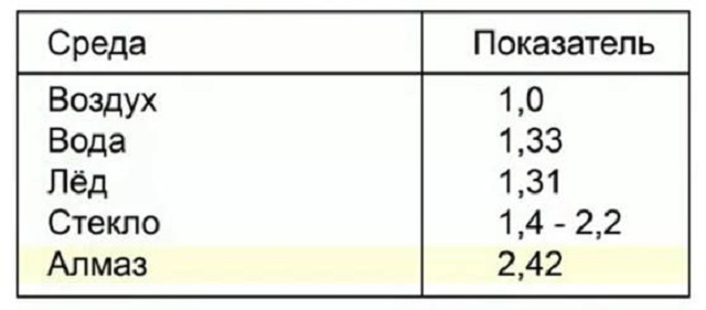
The speed of light propagation in a vacuum is greater than in any medium, so the absolute refractive index is always greater than unity (see table).


Rice. 12.5. If light enters the air from glass, then as the angle of incidence increases, the angle of refraction approaches 90°, and the brightness of the refracted beam decreases
When considering the transition of light from air to the medium, we will assume that the relative refractive index of the medium is equal to the absolute one.
The phenomenon of light refraction is used in the operation of many optical devices. You will learn about some of them later.
We use the phenomenon of total internal reflection of light
Let's consider the case when light passes from a medium with a higher optical density to a medium with a lower optical density (Fig. 12.5). We see that as the angle of incidence increases (α 2 >ι), the angle of refraction γ approaches 90°, the brightness of the refracted beam decreases, and the brightness of the reflected beam, on the contrary, increases. It is clear that if we continue to increase the angle of incidence, the angle of refraction will reach 90°, the refracted beam will disappear, and the incident beam will completely (without loss of energy) return to the first medium - the light will be completely reflected.
The phenomenon in which there is no refraction of light (light is completely reflected from a medium with a lower optical density) is called total internal reflection of light.
The phenomenon of total internal reflection of light is well known to those who have swum underwater with their eyes open (Fig. 12.6).

rice. 12.6. To an observer underwater, part of the surface of the water appears shiny, like a mirror
Jewelers have used the phenomenon of total internal reflection for centuries to enhance the attractiveness of gemstones. Natural stones are cut - they are given the shape of polyhedra: the edges of the stone act as “internal mirrors”, and the stone “plays” in the rays of light falling on it.
Total internal reflection is widely used in optical technology (Fig. 12.7). But the main application of this phenomenon is in fiber optics. If a beam of light is directed at the end of a solid thin “glass” tube, after repeated reflection, the light will come out at its opposite end, regardless of whether the tube is curved or straight. Such a tube is called a light guide (Fig. 12.8).
Light guides are used in medicine to study internal organs (endoscopy); in technology, in particular for identifying faults inside engines without disassembling them; for illuminating indoor spaces with sunlight, etc. (Fig. 12.9).
But most often, light guides are used as cables for transmitting information (Fig. 12.10). “Glass cable” is much cheaper and lighter than copper, it practically does not change its properties under the influence of the environment, and allows you to transmit signals over long distances without amplification. Today, fiber-optic communication lines are rapidly replacing traditional ones. When you watch TV or use the Internet, remember that a significant part of its path the signal travels along the “glass road”.


Learning to solve problems Problem. The light beam passes from medium 1 to medium 2 (Fig. 12.11, a). The speed of light propagation in medium 1 is 2.4 · 10 8 m/s. Determine the absolute refractive index of medium 2 and the speed of propagation of light in medium 2.
Analysis of a physical problem
From Fig. 12.11, and we see that at the interface between two media, light is refracted, which means that the speed of its propagation changes.
Let's make an explanatory drawing (Fig. 12.11, b), in which:
1) draw the rays given in the problem statement;
2) draw a perpendicular through the point of incidence of the beam to the interface between the two media;
3) let us denote the angle of incidence by α and the angle of refraction by γ.
The absolute refractive index is the index of refraction relative to vacuum. Therefore, to solve the problem, one should remember the value of the speed of light propagation in a vacuum and find the speed of light propagation in medium 2 (v 2).
To find v 2, we determine the sine of the angle of incidence and the sine of the angle of refraction.

Solution analysis. According to the conditions of the problem, the angle of incidence is greater than the angle of refraction, and this means that the speed of light in medium 2 is less than the speed of light in medium 1. Therefore, the results obtained are real.
Let's sum it up
A light beam falling on the interface between two media is divided into two beams. One of them - reflected - is reflected from the surface, obeying the laws of light reflection. The second - refracted - passes into the second medium, changing its direction.
Laws of light refraction:
1. The incident ray, the refracted ray and the perpendicular to the interface between two media drawn through the point of incidence of the ray lie in the same plane.
2. For two given media, the ratio of the sine of the angle of incidence α to the sine of the angle of refraction γ is a constant value:
The reason for the refraction of light is a change in the speed of its propagation when passing from one medium to another. The relative refractive index n 2 i shows how many times the speed of propagation of light in medium 1 is greater (or less) than the speed of propagation of light
![]()
in environment 2:
When light enters a medium from a vacuum, the refractive index n is called the absolute refractive index: n = c/v.
If, during the transition of light from medium 1 to medium 2, the speed of propagation of light decreased (that is, the refractive index of medium 2 is greater than the refractive index of medium 1: n 2 > n 1), then it is said that light passed from a medium with a lower optical density to a medium with a higher one optical density (and vice versa).
Security questions
1. What experiments confirm the phenomenon of light refraction at the interface between two media? 2. Formulate the laws of light refraction. 3. What is the reason for the refraction of light? 4. What does the refractive index of light show? 5. How is the speed of light related to the optical density of the medium? 6. Define the absolute refractive index.
Exercise No. 12
1. Transfer the rice. 1 per notebook. Assuming that medium 1 has a higher optical density than medium 2, for each case, schematically construct the incident (or refracted) ray, indicate the angle of incidence and the angle of refraction.

2. Calculate the speed of light propagation in diamond; water; air.
3. A ray of light falls from air into water at an angle of 60°. The angle between the reflected and refracted rays is 80°. Calculate the angle of refraction of the beam.
4. When we, standing on the shore of a reservoir, try to determine its depth by eye, it always seems smaller than it actually is. Using Fig. 2, explain why this is so.
5. How long does it take for light to reach the bottom of a lake 900 m deep to the surface of the water?
6. Explain the “trick” with the ring (coin) described at the beginning of § 12 (see Fig. 12.1).
7. A light beam passes from medium 1 to medium 2 (Fig. 3). The speed of light propagation in medium 1 is 2.5 · 10 8 m/s. Define:
1) which medium has the highest optical density;
2) refractive index of medium 2 relative to medium 1;
3) speed of light propagation in medium 2;
4) the absolute refractive index of each medium.
8. The consequence of the refraction of light in the Earth’s atmosphere is the appearance of mirages, as well as the fact that we see the Sun and stars slightly higher than their real position. Use additional sources of information and learn more about these natural phenomena.
Experimental tasks
1. “Coin trick.” Demonstrate the coin experiment (see Figure 12.1) to one of your friends or family and explain it.
2. “Water mirror”. Observe the total reflection of the light. To do this, fill the glass about halfway with water. Place an object, such as the body of a plastic pen, into the glass, preferably with an inscription. Holding the glass in your hand, place it at a distance of approximately 25-30 cm from your eyes (see picture). During the experiment, you should keep an eye on the body of the pen.
First, when you look up, you will see the entire body of the pen (both underwater and above-water parts). Slowly move the glass away from you without changing its height.
When the glass is far enough away from your eyes, the surface of the water will become mirror-like for you - you will see a mirror image of the underwater part of the handle body.
Explain the observed phenomenon.
LABORATORY WORK No. 4

Subject. Study of light refraction.
Purpose: to determine the refractive index of glass relative to air.
Equipment: glass plate with parallel edges, pencil, square with a millimeter scale, compass.
INSTRUCTIONS FOR OPERATION
Preparing for the experiment
1. Before performing work, remember:
1) safety requirements when working with glass objects;
2) laws of light refraction;
3) formula for determining the refractive index.

2. Prepare drawings to complete the work (see Fig. 1). To do this:
1) place the glass plate on a notebook page and use a sharpened pencil to outline the outline of the plate;
2) on the segment corresponding to the position of the upper refractive edge of the plate:
Mark point O;
Draw a straight line k through point O, perpendicular to this segment;
Using a compass, construct a circle with a radius of 2.5 cm with a center at point O;
3) at an angle of approximately 45°, draw a ray that will set the direction of the beam of light incident on point O; mark the intersection point of the ray and the circle with the letter A;
4) repeat the steps described in steps 1-3 twice more (perform two more drawings), first increasing and then decreasing the specified angle of incidence of the light beam.
Experiment
Strictly follow the safety instructions (see the flyleaf of the textbook).

1. Place a glass plate on the first circuit.
2. Looking at the AO beam through the glass, place point M at the bottom edge of the plate so that it appears to be located on the continuation of the AO beam (Fig. 2).
3. Repeat the steps described in steps 1 and 2 for two more circuits.
Processing of experiment results

Immediately enter the results of measurements and calculations into the table.
For each experiment (see Fig. 3):
1) draw the refracted ray OM;
2) find the point of intersection of the ray OM with the circle (point B);
3) from points A and B, lower perpendiculars to line k, measure the lengths a and b of the resulting segments and the radius of the circle r;
4) determine the refractive index of glass relative to air:

Analysis of the experiment and its results
Analyze the experiment and its results. Formulate a conclusion in which you indicate: 1) what physical quantity you determined; 2) what result did you get; 3) does the value of the obtained value depend on the angle of incidence of light; 4) what are the reasons for the possible error of the experiment.

Creative task
Using Fig. 4, think over and write down a plan for conducting an experiment to determine the refractive index of water relative to air. If possible, conduct an experiment.
Assignment with an asterisk
![]()
where p meas is the value of the refractive index of glass relative to air obtained during the experiment; n is the tabulated value of the absolute refractive index of the glass from which the plate is made (check with your teacher).
This is textbook material
Processes that are associated with light are an important component of physics and surround us everywhere in our everyday life. The most important in this situation are the laws of reflection and refraction of light, on which modern optics is based. The refraction of light is an important part of modern science.
Distortion effect
This article will tell you what the phenomenon of light refraction is, as well as what the law of refraction looks like and what follows from it.
Basics of a physical phenomenon
When a beam falls on a surface that is separated by two transparent substances that have different optical densities (for example, different glasses or in water), some of the rays will be reflected, and some will penetrate into the second structure (for example, they will propagate in water or glass). When moving from one medium to another, a ray typically changes its direction. This is the phenomenon of light refraction.
The reflection and refraction of light is especially visible in water.

Distortion effect in water
Looking at things in water, they appear distorted. This is especially noticeable at the boundary between air and water. Visually, underwater objects appear to be slightly deflected. The described physical phenomenon is precisely the reason why all objects appear distorted in water. When the rays hit the glass, this effect is less noticeable.
Refraction of light is a physical phenomenon that is characterized by a change in the direction of movement of a solar ray at the moment it moves from one medium (structure) to another.
To improve our understanding of this process, consider an example of a beam hitting water from air (similarly for glass). By drawing a perpendicular line along the interface, the angle of refraction and return of the light beam can be measured. This index (angle of refraction) will change as the flow penetrates the water (inside the glass).
Pay attention! This parameter is understood as the angle formed by a perpendicular drawn to the separation of two substances when a beam penetrates from the first structure to the second.

Beam Passage
The same indicator is typical for other environments. It has been established that this indicator depends on the density of the substance. If the beam falls from a less dense to a denser structure, then the angle of distortion created will be greater. And if it’s the other way around, then it’s less.
At the same time, a change in the slope of the decline will also affect this indicator. But the relationship between them does not remain constant. At the same time, the ratio of their sines will remain a constant value, which is reflected by the following formula: sinα / sinγ = n, where:
- n is a constant value that is described for each specific substance (air, glass, water, etc.). Therefore, what this value will be can be determined using special tables;
- α – angle of incidence;
- γ – angle of refraction.
To determine this physical phenomenon, the law of refraction was created.
Physical law
The law of refraction of light fluxes allows us to determine the characteristics of transparent substances. The law itself consists of two provisions:
- first part. The beam (incident, modified) and the perpendicular, which was restored at the point of incidence on the boundary, for example, of air and water (glass, etc.), will be located in the same plane;
- second part. The ratio of the sine of the angle of incidence to the sine of the same angle formed when crossing the boundary will be a constant value.

Description of the law
In this case, at the moment the beam exits the second structure into the first (for example, when the light flux passes from the air, through the glass and back into the air), a distortion effect will also occur.
An important parameter for different objects
The main indicator in this situation is the ratio of the sine of the angle of incidence to a similar parameter, but for distortion. As follows from the law described above, this indicator is a constant value.
Moreover, when the value of the decline slope changes, the same situation will be typical for a similar indicator. This parameter is of great importance because it is an integral characteristic of transparent substances.
Indicators for different objects
Thanks to this parameter, you can quite effectively distinguish between types of glass, as well as various precious stones. It is also important for determining the speed of light in various environments.
Pay attention! The highest speed of light flow is in a vacuum.
When moving from one substance to another, its speed will decrease. For example, in diamond, which has the highest refractive index, the speed of photon propagation will be 2.42 times higher than that of air. In water, they will spread 1.33 times slower. For different types of glass, this parameter ranges from 1.4 to 2.2.
Pay attention! Some glasses have a refractive index of 2.2, which is very close to diamond (2.4). Therefore, it is not always possible to distinguish a piece of glass from a real diamond.
Optical density of substances
Light can penetrate through different substances, which are characterized by different optical densities. As we said earlier, using this law you can determine the density characteristic of the medium (structure). The denser it is, the slower the speed at which light will propagate through it. For example, glass or water will be more optically dense than air.
In addition to the fact that this parameter is a constant value, it also reflects the ratio of the speed of light in two substances. The physical meaning can be displayed as the following formula:
This indicator tells how the speed of propagation of photons changes when moving from one substance to another.
Another important indicator
When a light flux moves through transparent objects, its polarization is possible. It is observed during the passage of a light flux from dielectric isotropic media. Polarization occurs when photons pass through glass.

Polarization effect
Partial polarization is observed when the angle of incidence of the light flux at the boundary of two dielectrics differs from zero. The degree of polarization depends on what the angles of incidence were (Brewster's law).
Full internal reflection
Concluding our short excursion, it is still necessary to consider such an effect as full internal reflection.

The phenomenon of full display
For this effect to appear, it is necessary to increase the angle of incidence of the light flux at the moment of its transition from a more dense to a less dense medium at the interface between substances. In a situation where this parameter exceeds a certain limiting value, then photons incident on the boundary of this section will be completely reflected. Actually, this will be our desired phenomenon. Without it, it was impossible to make fiber optics.
Conclusion
The practical application of the behavior of light flux has given a lot, creating a variety of technical devices to improve our lives. At the same time, light has not yet revealed all its possibilities to humanity and its practical potential has not yet been fully realized.
 How to make a paper lamp with your own hands
 How to check the performance of an LED strip
At the interface between two transparent media, along with the reflection of light, refraction is observed; light, passing into another medium, changes the direction of its propagation.
Refraction of a light beam occurs when it is incident at an oblique angle on the interface (though do not always read further about total internal reflection). If the ray falls perpendicular to the surface, then there will be no refraction in the second medium; the ray will retain its direction and will also go perpendicular to the surface.
4.3.1 Law of refraction (special case)
We will start with the special case when one of the media is air. This is exactly the situation that occurs in the vast majority of problems. We will discuss the corresponding special case of the law of refraction, and only then we will give its most general formulation.
Suppose that a ray of light traveling in air falls obliquely onto the surface of glass, water or some other transparent medium. When passing into the medium, the beam is refracted, and its further path is shown in Fig. 4.11.
Wednesday O
Rice. 4.11. Refraction of a beam at the air-medium interface
At the point of incidence O, a perpendicular (or, as they also say, normal) CD is drawn to the surface of the medium. The ray AO, as before, is called the incident ray, and the angle between the incident ray and the normal is the angle of incidence. Ray OB is a refracted beam; The angle between the refracted ray and the normal to the surface is called the angle of refraction.
Any transparent medium is characterized by a value n, which is called the refractive index of this medium. The refractive indices of various media can be found in tables. For example, for glass n = 1;6, and for water n = 1;33. In general, any medium has n > 1; The refractive index is equal to unity only in a vacuum. For air, n = 1.0003, therefore, for air, with sufficient accuracy, we can assume n = 1 in problems (in optics, air is not very different from vacuum).
Law of refraction (transition ¾air-medium¿).
1) The incident ray, the refracted ray, and the normal to the surface drawn at the point of incidence lie in the same plane.
2) The ratio of the sine of the angle of incidence to the sine of the angle of refraction is equal to the refractive index
environment:

Since n > 1, it follows from relation (4.1) that sin > sin, that is, > the angle of refraction is less than the angle of incidence. Remember: when moving from air to a medium, the ray, after refraction, goes closer to the normal.
The refractive index is directly related to the speed v of light propagation in a given medium. This speed is always less than the speed of light in vacuum: v< c. И вот оказывается,
We will understand why this happens when we study wave optics. In the meantime, combi-
Let us set up formulas (4.1) and (4.2): | |||||
Since the refractive index of air is very close to unity, we can assume that the speed of light in air is approximately equal to the speed of light in a vacuum c. Taking this into account and looking at formula (4.3), we conclude: the ratio of the sine of the angle of incidence to the sine of the angle of refraction is equal to the ratio of the speed of light in air to the speed of light in the medium.
4.3.2 Reversibility of light rays
Now let's consider the reverse path of the beam: its refraction when passing from the medium to the air. The following useful principle will help us here.
The principle of reversibility of light rays. The beam path does not depend on whether the beam is propagating in the forward or backward direction. Moving in the opposite direction, the beam will follow exactly the same path as in the forward direction.
According to the principle of reversibility, when transitioning from a medium to air, the ray will follow the same trajectory as during the corresponding transition from air to medium (Fig. 4.12) The only difference between Fig. 4.12 and Fig. 4.11 is that the direction of the ray has changed to the opposite.
Wednesday O
Rice. 4.12. Refraction of a beam at the interface between medium and air
Since the geometric picture has not changed, formula (4.1) will remain the same: the ratio of the sine of the angle to the sine of the angle is still equal to the refractive index of the medium. True, now the angles have changed roles: the angle has become the angle of incidence, and the angle has become the angle of refraction.
In any case, no matter how the beam goes from air to medium or from medium to air, the following simple rule applies. We take two angles: the angle of incidence and the angle of refraction; the ratio of the sine of the larger angle to the sine of the smaller angle is equal to the refractive index of the medium.
![]()
We are now fully prepared to discuss the law of refraction in the most general case.
4.3.3 Law of refraction (general case)
Let light pass from medium 1 with refractive index n1 to medium 2 with refractive index n2. A medium with a higher refractive index is called optically denser; Accordingly, a medium with a lower refractive index is called optically less dense.
Moving from an optically less dense medium to an optically more dense one, the light beam, after refraction, goes closer to the normal (Fig. 4.13). In this case, the angle of incidence is greater than the angle of refraction: > .
Rice. 4.13. n1< n2 ) >
On the contrary, moving from an optically denser medium to an optically less dense one, the beam deviates further from the normal (Fig. 4.14). Here the angle of incidence is less than the angle of refraction:
Rice. 4.14. n1 > n2)<
It turns out that both of these cases are covered by one formula by the general law of refraction, which is valid for any two transparent media.
Law of refraction.
1) The incident ray, the refracted ray and the normal to the interface between the media, drawn
V point of impact lie in the same plane.

2) The ratio of the sine of the angle of incidence to the sine of the angle of refraction is equal to the ratio of the refractive index of the second medium to the refractive index of the first medium:
It is easy to see that the previously formulated law of refraction for the air-medium transition is a special case of this law. In fact, putting n1 = 1 and n2 = n in formula (4.4), we arrive at formula (4.1).
Let us now remember that the refractive index is the ratio of the speed of light in a vacuum to the speed of light in a given medium: n1 = c=v1, n2 = c=v2. Substituting this into (4.4), we get:
Formula (4.5) naturally generalizes formula (4.3). The ratio of the sine of the angle of incidence to the sine of the angle of refraction is equal to the ratio of the speed of light in the first medium to the speed of light in the second medium.
4.3.4 Total internal reflection
When light rays pass from an optically denser medium to an optically less dense one, an interesting phenomenon, total internal reflection, is observed. Let's figure out what it is.
For definiteness, we assume that light comes from water into air. Let us assume that in the depths of the reservoir there is a point source of light S, emitting rays in all directions. We will look at some of these rays (Fig. 4.15).
S B 1
Rice. 4.15. Total internal reflection
Beam SO1 hits the water surface at the smallest angle. This beam is partially refracted (ray O1 A1) and partially reflected back into the water (ray O1 B1). Thus, part of the energy of the incident beam is transferred to the refracted beam, and the remaining energy is transferred to the reflected beam.
The angle of incidence of the SO2 beam is greater. This beam is also divided into two beams, refracted and reflected. But the energy of the original beam is distributed between them differently: the refracted beam O2 A2 will be dimmer than the beam O1 A1 (that is, it will receive a smaller share of energy), and the reflected beam O2 B2 will be correspondingly brighter than the beam O1 B1 (it will receive a larger share energy).
As the angle of incidence increases, the same pattern is observed: an increasingly larger share of the energy of the incident beam goes to the reflected beam, and an ever smaller share to the refracted beam. The refracted beam becomes dimmer and dimmer, and at some point disappears completely!
This disappearance occurs when the angle of incidence reaches 0, which corresponds to the angle of refraction 90. In this situation, the refracted beam OA would have to go parallel to the surface of the water, but there is nothing left to go; all the energy of the incident beam SO went entirely to the reflected beam OB.
With a further increase in the angle of incidence, the refracted beam will even be absent.
The described phenomenon is complete internal reflection. Water does not release rays with angles of incidence equal to or exceeding a certain value 0; all such rays are completely reflected back into the water. Angle0 is called the limiting angle of total reflection.
The value 0 is easy to find from the law of refraction. We have:
sin 0 | ||||||||||
But sin 90 = 1, so | ||||||||||
sin 0 | ||||||||||
0 = arcsin | ||||||||||
So, for water the limiting angle of total reflection is equal to:
0 = arcsin1; 1 33 48;8:
You can easily observe the phenomenon of total internal reflection at home. Pour water into a glass, lift it and look at the surface of the water just below through the wall of the glass. You will see a silvery sheen to the surface due to total internal reflection; it behaves like a mirror.
The most important technical application of total internal reflection is fiber optics. Light rays launched into a fiber optic cable (light guide) almost parallel to its axis fall onto the surface at large angles and are completely reflected back into the cable without loss of energy. Repeatedly reflected, the rays travel further and further, transferring energy over a considerable distance. Fiber optic communications are used, for example, in cable television networks and high-speed Internet access.
4.1. Basic concepts and laws of geometric optics
Laws of light reflection.First law of reflection:
the incident and reflected rays lie in the same plane with the perpendicular to the reflecting surface, restored at the point of incidence of the ray.
Second law of reflection:
the angle of incidence is equal to the angle of reflection (see Fig. 8).
α - angle of incidence, β - angle of reflection.
Laws of light refraction. Refractive index.
First law of refraction:
the incident ray, the refracted ray and the perpendicular reconstructed at the point of incidence to the interface lie in the same plane (see Fig. 9). 
Second law of refraction:
the ratio of the sine of the angle of incidence to the sine of the angle of refraction is a constant value for two given media and is called the relative refractive index of the second medium relative to the first. 
The relative refractive index shows how many times the speed of light in the first medium differs from the speed of light in the second medium: 
Total reflection.
If light passes from an optically denser medium to an optically less dense one, then if the condition α > α 0 is met, where α 0 is the limiting angle of total reflection, the light will not enter the second medium at all. It will be completely reflected from the interface and remain in the first medium. In this case, the law of light reflection gives the following relationship: 
4.2. Basic concepts and laws of wave optics
Interference is the process of superposition of waves from two or more sources on each other, as a result of which the wave energy is redistributed in space. To redistribute wave energy in space, it is necessary that the wave sources be coherent. This means that they should emit waves of the same frequency and the phase shift between the oscillations of these sources should not change over time.Depending on the path difference (∆) at the point of overlap of the rays, maximum or minimum interference. If the path difference of rays from in-phase sources ∆ is equal to an integer number of wavelengths mλ (m- integer), then this is the maximum interference:
if there is an odd number of half-waves, the minimum interference is:

Diffraction called the deviation in wave propagation from the rectilinear direction or the penetration of wave energy into the region of the geometric shadow. Diffraction is clearly observed in cases where the sizes of obstacles and holes through which the wave passes are commensurate with the wavelength.
One of the optical instruments that is good for observing light diffraction is diffraction grating. It is a glass plate on which strokes are applied at equal distances from each other with a diamond. Distance between strokes - lattice constant d. Rays passing through the grating are diffracted at all possible angles. The lens collects rays coming at the same diffraction angle at one of the points of the focal plane. Coming at a different angle - at other points. Superimposed on each other, these rays give a maximum or minimum of the diffraction pattern. The conditions for observing maxima in a diffraction grating have the form:
Where m- integer, λ - wavelength (see Fig. 10).